Software Defined Radio Receiver by Carlos Pérez-Penichet | complexperiments.net
A Software defined radio (SDR) is a radio communication system where the signal processing is done in the digital domain. This project aims at creating a simple, but functional, software defined radio receiver. This is the final project for the Complimentary Electronics course I took from October to December, 2010. The goal is to be able to receive and reproduce standard radio (AM) broadcast signals with a desktop computer running LabView and equipped with a data acquisition card.

The ideal Software Defined Radio directly samples the radio signal from the antenna. However this can not be done in practice due to the limitations of real ADCs in dynamic range and bandwidth. Practical Software Defined Radio implementations use a radio front end to condition the signal for the ADC and then digitize it as soon as possible in order to maximize the flexibility provided by the software.
Most radio receivers work with a scheme known as super heterodyne. In it, the received signal is mixed with the output of a local variable-frequency oscillator in such a way that the desired station can be tuned by varying the frequency of the local oscillator. The result of mixing is that the received signal is transported to a fixed intermediate frequency. This approach has the advantage that the band-pass filters used to achieve the needed levels of selectivity and adjacent frequency rejection only need to be tuned to the fixed intermediate frequency. In AM receptors the intermediate frequency is usually 455kHz. In order to keep the amount of electronics to build to a minimum I intend to extract the IF of a commercial radio receiver.
Implementation
 The data acquisition card I have access to (the DaqBoard 1000 from IoTech) has a maximum of 200ksps sampling rate. This specification means that I have enough bandwidth to receive AM signals but not FM.
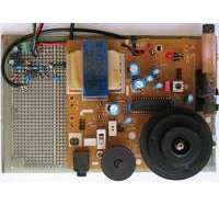
As I mentioned earlier I will use the circuit of a commercial radio receiver to extract the Intermediate Frequency. The receiver I have is based on the CXA1019 chip from Sony. The CXA1019 is "a one-chip FM/AM radio IC". It has an RF amplifier, mixer and oscillator, also features an IF amplifier and the rest of the sections a normal radio usually has.
My idea is to take the IF signal at the IF amplifier output, amplify it even further and feed it to the acquisition board to be digitized. Once the signal is in the digital domain, I can implement filtering and demodulation algorithms so I can play the demodulated signal through the computer's speakers. The IF in the CXA1019 is the usual 455kHz and because the maximum sampling rate of the DaqBoard 1000 is 200kHz I had to recur to the under sampling technique. Under sampling the 455kHz IF signal at 200kHz I get an alias at 55kHz which is centered in the band of the card.
IF Amplifier
 To boost the IF from the CXA1019, I built an amplifier on the MAX dual based op-amp. This is a dual low-noise, low-distortion, wide-band operational amplifier. You can download the eagle design project for the amplifier here. The amplifier was built in two stages because the GBWP does not allow for the needed gain in a single phase.
By recommendation of Claro Noda, and with his help, I also made the amplifier work as a Variable Gain Amplifier (VGA). By doing this I also had the possibility of controlling the gain of the amplifier from the software through one of the DAC ports of the data acquisition board affectively turning it into an Automatic Gain Control (AGC) system. Thus the dynamic range of the receiver is highly extended while, at the same time, I have the possibility of estimating the strength of the received signal (RSSI) by looking at the gain needed to achieve a given signal level.
Signal processing
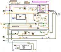
 Once digitized, a digital band-pass filter is applied. This filter is important because the under sampling may introduce a lot of noise by aliasing. I tried three different demodulation algorithms for AM signals, namely: An envelope detector, a synchronous detector and a quadrature synchronous detector. Download the whole LabView project here. While the quality of the sound is not impressive, I was thrilled when I could hear the sound of the standard radio stations coming out from the speakers. Here is a sample of the audio.
Perspectives
In the future I would like to implement a way to tune the radio from the computer. For this I would have to replace the oscillating tanks in the commercial radio with two VCOs. One way I have found to do this is by simply replacing the tunable capacitors in C1 and C4, each, by two varactors placed back to back. So far I have not been able to get varactors with the right range of capacity. This would allow me to do interesting things such as auto tunning.
more...
If you want to know a little more about this project you can download the slideshow (Spanish). Do not hesitate to write if you have any question or idea.
Downloads
Latest Publications
- TagAlong: Efficient Integration of Battery-free Sensor Tags in Standard Wireless Networks. In ACM/IEEE IPSN ’20.Details and Download
- A Fast Carrier Scheduling Algorithm for Battery-free Sensor Tags in Commodity Wireless Networks. In IEEE INFOCOM ’20.Details and Download
- Modelling Battery-free Communications for the Cooja Simulator. In ACM EWSN ’19.Details and Download
- Battery-free 802.15.4 Receiver. In ACM/IEEE IPSN ’18.Details and Download
- LoRea: A Backscatter Architecture That Achieves a Long Communication Range. In ACM SenSys ’17.Details and Download